: injection molding machine manufacturer/supplier")
: injection molding machine manufacturer/supplier")

Product Info
Engineering plastic is industrial plastic made to be industrial parts or shell. Their strength, impact resistance, heat resistance, hardness and aging resistance are all good. In Japan, the industries define them as “high performance plastics used as mechanical parts with heat resistance at 100℃ or higher and mainly for industrial use”.
Their property include:
- Thermal Property: High glass transfer temperature (Tg) and melting point (Tm), high temp.Deformation, high long-term use temperature (UL-746B), large use temperature range, low heat expansion coefficient.
- Mechanical property: high strength, high mechanical mode, low creep, abrasion resisting, fatigue resisting.
- Others: Good chemical resistance, good electric resistance, combustion resistance, weather resistance and dimensional stability.
Those being used as universal plastics include Polycarbonate, PC, Nylon, Polyamide, PA, Polyacetal, Polyoxy Methylene, POM, M-Poly Phenylene Oxide, M-PPE, PETP, PBTP, Polyphenylene Sulfide, PPS, and in thermosetting plastics there are saturated polyester, phenolic plastic and epoxy. They have stretch strength all exceeding 50Mpa and tensile strength over 500kg/cm2, impact resistance exceeding 50J/m, bending elasticity at 24000kg/cm2, load flexible temperature over 100℃. Good hardness and aging property. When PP has the hardness and cold resistance improved, it can be categorized into engineering plastics. Also included are fluorous plastics, which are low strength, good heat resistance and medicine resistance, silicone molten compound of good heat resistance, polyetherimide, polyimid, Polybismaleimide、Polysufone(PSF)、PES、PP Plastic, M-Millitic Amine Plastic, BT Resin、PEEK, PEI, crystalline plastic. Due to difference in chemical structure, medicine resistance, friction characteristics and electric characteristic are different. Due also to the molding property, part of them are suitable for all kinds of molding, and some of them fit only to certain types, which restricted their applicability. Thermosetting engineering plastics are with poor impact resistance, so the normally are added with fiberglass. Other than PC, which has high impact resistance, they normally have low elongation, hard and brittle, but if they are added with 20 – 30 % fiberglass, they can be improved.
Plastic is a aggregate of slim, linear polymer compound. The regularity of molecular array is called crystalline, the degree of crystallization, which can be measured with X ray. Organic compound has more complicate construction, and the bonds are various (linear, curl, folding, spiral, etc) and this leads to great change in construction due to molding conditions. Plastics with high crystallization are Crystalline Plastics, and the interaction is high between molecular and become tough plastic. To be crystallized and correct regular array, the volume becomes smaller and the shrinkage and heat expansion rates become larger. Hence, the higher the crystalline is, the poorer the transparency and the higher the strength.
Crystalline Plastics has apparent melting point (Tm), at solid state, it is arrayed regularly, the strength is higher and the tensile is better. When melted, there is higher specific volume change and easy to shrink after solidification. The inner stress is less easy to release. The molded product is non-transparent. The heat dissipation during molding is slow. Production with cold mold has large shrinkage rate, but smaller in hot mold production. In contrast, there is Non-Crystalline Plastics. It does not have apparent melting point, and the molecular is not regularly arranged in its solid state. When melted, there is small change in specific volume, and not likely to shrink when solidified. The product has good transparency. The higher the material temperature, the yellowish the gloss is. Heat dissipation is fast during molding. The following is comparison of property of the two different kinds.

The full name of MI is Melt Flow Index, or Melt Index, a value indicating the fluidity of plastic at working. It is established by ASTM adopting the method normally employed by Du Pont is testing characteristics of plastics. The testing method is the weight in gram of plastic material flowing through a round tube of 2.1mm within 10 minutes under certain temperature and pressure (they are different for different type of plastic materials). The higher the value the better the working fluidity of the specific plastic material, or it is poorer. The most frequent test standard is ASTM D 1238. The measuring instrument of this standard is Melt Indexer, with construction of one trough for plastic material; a tube of 2.095mm dia. and 8mm long is fitted to the end of the trough. When heated to a certain temperature, a piston at the top apply certain weight and press down to measure the weight of the material being squeezed out in 10 minutes, which is the MI. Sometimes, it is indicated as 25g / 10min, clearly indicate its MI is 25, and is 25g being squeezed out in 10 min. The MI values of frequent used plastics are ranged between 1 and 25. The higher MI the lower the viscosity and mole weight, and the smaller MI is, the plastic has higher viscosity and large mole weight.
Glass transition temperature, Tg, is a kind of Transition temperature. AT Tg, polymer will demonstrate rubber state at higher temperature to hard and brittle glass-like state at lower temperature.
Crystalline plastics have apparent Tg and latent heat. A polymer in rubber or glass state is depends on Tg and the temperature in use, so Tg is an important indicator in the use of polymer.
The following are Tg of some of plastic materials.
Heat deflection temperature, HDT, means , under pressure, the highest temperature the plastics maintain profile unchanged. Generally, this is indicated by Short Term Heat Resistance of plastics. When safety factor is taken into consideration, the highest temperature at use shall be 10℃ less than HDT. The most frequent used measure is ASTM D648 (apply temperature rise of 2℃/min at the center of a standard of 127×13×3mm, under 455kPa 1820kPa charge, till the deformation rate is 0.25mm). For non-crystalline plastics, HDT is 10~20℃ Tg; to crystalline plastics, HDT is close to Tm. Normally, when fiber reinforcement is added, the HDT will rise, because the fiber can greatly increase the mechanical strength of plastics, so the HDT will rise drastically during temperature rise flexibility test.
Shrinkage rate means the deviation in dimensions of the molded , cooled and solidified products from the dimension of original molds measured in percentage, this can be measured per ASTM D955.
The shrinkage rate shall be considered firstly at the design of mold, so to avoid the product discrepancy due to dimensional discrepancy.
The scope of application of certain frequently used plastics:
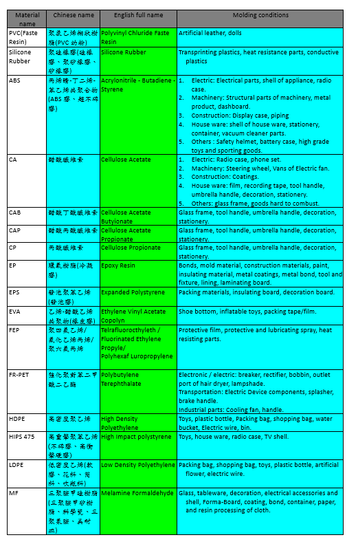
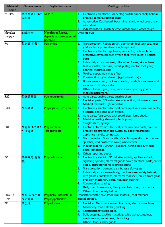
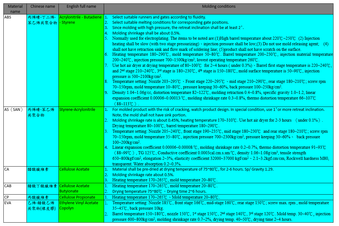
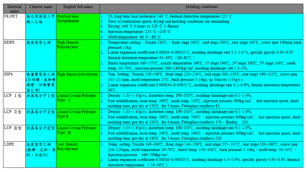
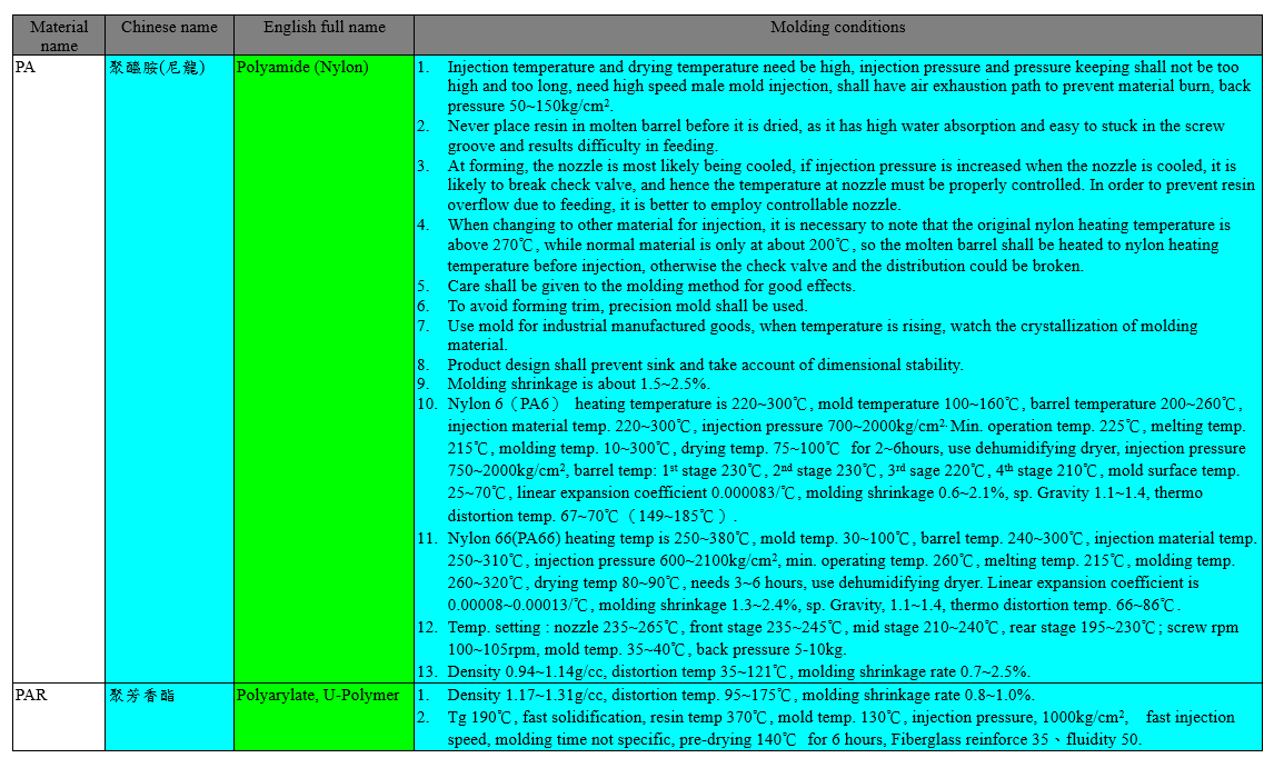
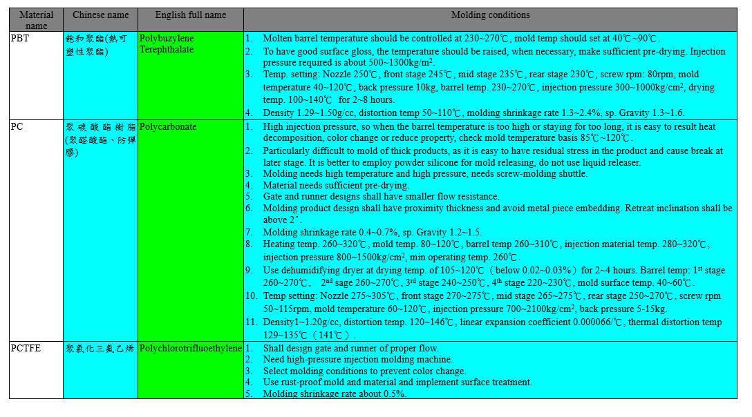
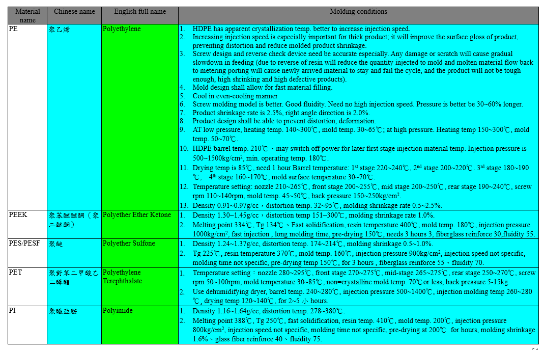
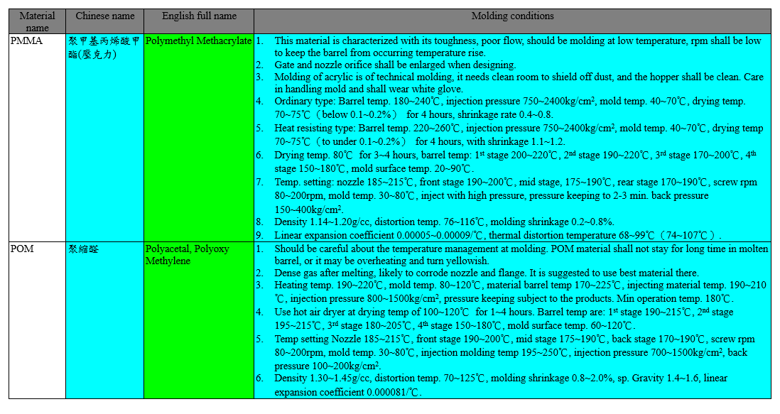
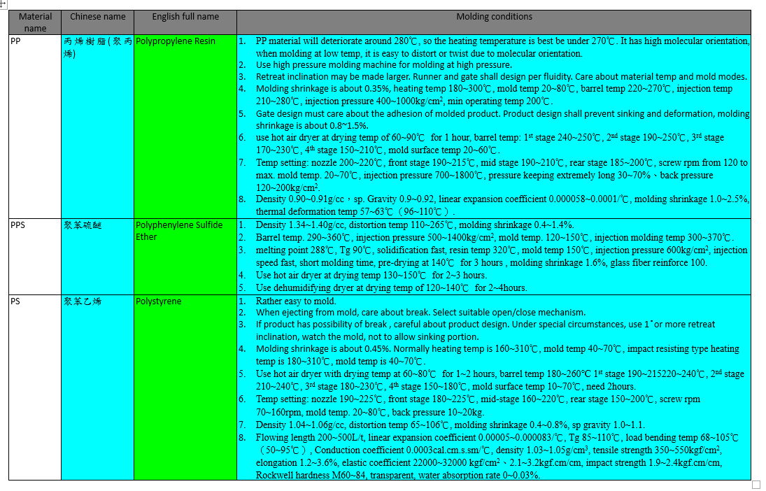
The molding conditions of some plastic materials are listed in the following tables:
Injection mold can be split into hot runner mold and cold runner mold. The former is also called as “ No Runner Mold” which insert heater into sprue or runner to keep the molten resin at this portion to coagulate but flowing. After each injection, the material in runner will remain there and taken out on the product,which means during the resin is the mold cavity, the resin in the runner remain molten, and when open mold, only the product is taken out. The later type of mold, the resin in the runner cools down together with the resin in the mold cavity, and takes out together. It is further split into Cold Runner 2-platen mold and Cold runner 3-platen mold.
In cold runner 2-platen mold, the product and the gate are taken out together, except submersible gate, the product and runner is connected. In cold runner 3-platen mold, after opening the mold, the product and the gate are taken out together also, but mostly with point gate. The difference between them is that the runner is set to the other plane of mold splitting surface in case of cold runner 3-platen mold, which means that except Core and Cavity, there is another a runner releasing plate. The mold is basically consisted of these 3 mold platens, and the fixed mold plate and runner releasing plate are sliding along the long guide key on the installation plate of the fixed portion
When injection molding, the resin in sprue and in runner are maintained in molten state by special method,and when the product is released from mold, the runner still maintain in the mold. This is so-called hotrunner injection molding. The benefit and short are listed in the following table.
When taking product out of female mold, the mold has to be break into two halves, the parting line, PL is where theyare separate, it is also called division surface or mold split line. Base on this line, the fixed portion is called fixed mold, or female, and the movable part is called moving mold or male. When the PL is decided, the profile of female cavity and male cavity can be determined. And determine it needs side concentric type.
It can be used to understand the difficulty of mold design. When selecting PL, the following shall be attended:
- Select less prominent location or shape to avoid affecting the appearance of molded product.
- At the mold opening, it is not recommended to have dead corner, to avoid increasing mold
cost.
- Should be at the location easy for through working, easy to process or easy to finish product.
- The gate shape and location shall be taken into consideration.
The function of runner system is to guide molten resin injecting from the nozzle of injection molding machine into mold cavity . This system consists of sprue, main runner, branch runner, gate. The design and preparation of runner system have substantial effects on quality, precision, appearance and molding cycle. Sprue is the filling port of molten resin. In order to detach from the mold, it is normally design with 2°~4°chamfer. Main runner and branch runner is the path for the molten resin to flow into mold cavity, and here the fluidity and heat loss shall receive special consideration. Gate is the entrance of molten resin enters mold cavity. The design of gate has great effect on the molding and inner stress of product. Detailed runner system is shown in the following figure.
Cold slug well is also called “ Material Stay”. The purpose is to prevent flow mark on the next molding product left by molten resin. Generally, the nozzle tip of injection ma chine has small molten material left, which will be solidified before next injection. If it enters molded product, it will leave flow mark. To prevent it, the solidified material at the front of injection material is kept in cold slug well, to prevent hurting the appearance of product. Cold slug well is normally located at the junction of sprue and main runner, as show in above figure. So, the cold slug well is to keep the colder material at the front tip of injection nozzle of last molding, and allow the molten material with even temperature injected into mold cavity. This helps to even the density and quality of products.
Gate has substantial effect on the molding feature and internal stress. Normally suitable type is selected per the shape of product molded. They may be split into Restricted Gate and Non-Restricted Gate. The former has narrow entrance between runner and mold cavity. It is easy for processing and to cut off the molded products from runner. It helps to reduce residual stress. It is easy to balance multiple cavities gates in multi-product in on shot. This type is generally adopted when he molten resin in mold cavity is not likely to reverse. Under this category, there are Side Gate, Overlap Gate, Tab Gate, Fan Gate, Film Gate, Ring Gate, Disk Gate, Point Gate and Submarine Gate. The later is gate for molten material injected directly into cavity from sprue. This is the representative of non-restricted gate. The type, location, size, number of gate has direct effect on the molded products in appearance, deformation, retraction and strength. Therefore, in design, the following shall be taken in consideration:
- Shape of Gate:
Shape of gate affects the molten resin fluidity inside cavity, the appearance of molded product, and the material flow direction. It is therefore necessary to select type of gate base on type of material or shape of molded products and the effect on flow direction.
- Location and number of gates:
(1) The location of gate shall allow molten material to run throughout all part of the mold,
and it is better to be in the center or the thick part of molded products.
(2) The hole on molded product will have key on the mold. Do not let the injected material
bend or shift those keys.
(3) When at two or more locations, they shall not allow the welding line or air bubble damage
appearance of product and reduce the strength.
(4) Residual stress tends to concentrate adjacent to gate, which could become bristle and
crack. So it is recommended not to select the location sustaining force.
(5) Selection the location where it is not prominent on the product surface, easier to process.
3.Type of Gate (Shape):
In its function, gates may be separated into Restricted Gate and Non-Restricted Gate. The former is build a narrow part at the joint between main/branch runner and the mold to hold the flow of material; the later has sprue for material to flow directly into the entrance of female mold. Ordinarily restricted gate is more selected. The features, shorts and benefits are listed in the following table.